
Mastering Circuits!
Don’t know about the Basic Laws of Electrical Circuits yet!
Read this: Basic Laws of Electrical Circuits
Ready to put your theoretical knowledge to the test?
Solved Problems on Ohm’s Law
In this section, we focus on the
Problem 1
Pb-1: Design a problem, complete with a sloution, to help students to better understand Ohm’s Law. Use at least two resistors and one voltage source. Hint, you could use both resistors at once or one at a time, it is up to you. Be creative.
Solution:
The Scenario: You are building a custom flashlight using a standard 9 \ V battery. You have a high power LED bulb (we will treat this as Resistor 1) that you want to use.
- Test 1: When you connect the LED directly to the 9 \ V battery, you measure a current of 0.3 \ A . However, the LED gets dangerously hot.
- Test 2: To fix this, you add a safety resistor (Resistor 2) in series with the LED. After measuring the circuit again, the current has successfully dropped to 0.1 \ A .

Figure 1 – Circuit diagram for Pb-1
Your Questions:
Using Ohm’s Law, answer the following three questions:
(a) Based on Test 1, what is the internal resistance of the LED bulb (Resistor 1)?
(b) Based on current drop in Test 2, what is the resistance value of the safety resistor you added (Resistor 2)?
(c) In the final circuit (Test 2), what is the voltage drop across just the safety resistor?
\small \begin{aligned} (a) \quad &\text{We know,} \\[2ex] &\quad R = \frac{v}{i} \\[2ex] &\quad \therefore R_1 = \frac{9}{0.3} = 30 \ \Omega \\[2ex] (b) \quad &\text{The current drop in Test 2 is: } 0.1 \ A \\[2ex] &\quad R_{total} = \frac{9}{0.1} = 90 \ \Omega \\[2ex] &\text{As it is a series circuit,} \\[2ex] &\quad \therefore R_2 = 90 - 30 = 60 \ \Omega \\[2ex] (c) \quad &\text{Voltage drop across safety resistor:} \\[2ex] &\quad v_2 = 0.1 \times R_2 = 0.1 \times 60 \\[2ex] &\quad \therefore v_2 = 6 \ V \end{aligned}
Problem 2
Pb-2: Find the hot resistance of a light bulb rated 60 \ W , 120 \ V .
Solution:
\small \begin{aligned} &\text{We know,} \\[2.5ex] &\quad p = \frac{v^2}{R} \Rightarrow R = \frac{v^2}{p} = \frac{(120)^2}{60} \\[2.5ex] &\quad \therefore R = 240 \ \Omega \end{aligned}
Problem 3
Pb-3: A bar of silicon is 4 \ cm long with a circular cross section. If the resistance of the bar is 240 \ \Omega at room temperature, what is the cross-sectional radius of the bar? [Resistivity of Silicon, \rho = 6.4 \times 10^{2} \ \Omega m ].
Solution:
\small \begin{aligned} &\text{We know,} \\[2.5ex] &\quad R = \rho \frac{L}{A} \Rightarrow 240 = 6.4 \times 10^2 \times \frac{4 \times 10^{-2}}{\pi r^2} \\[2.5ex] &\quad \therefore r = 0.184 \ m \end{aligned}
Problem 4
Pb-4: (a) Calculate current i in Fig. 2 when the switch is in position 1.
(b) Find the current when the switch is in position 2.
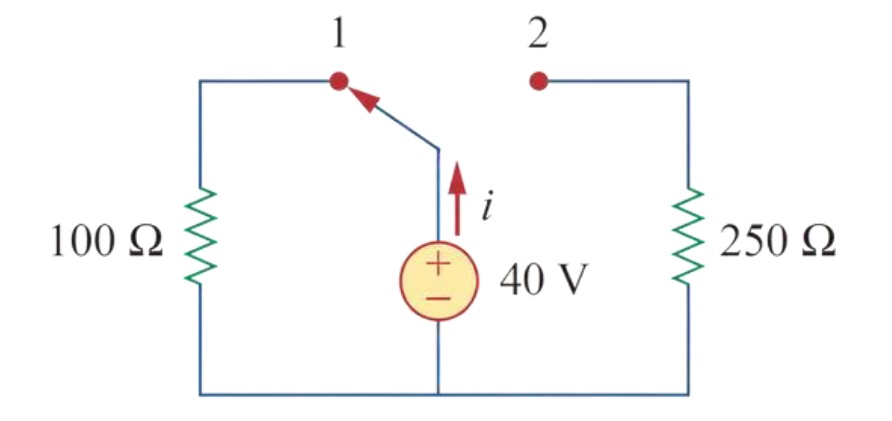
Figure 2 - Circuit diagram for Pb-4
Solution:
(a) When the switch is in position 1,
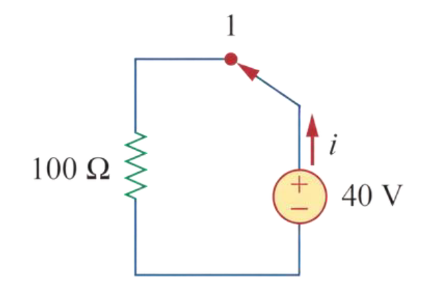
Figure 3 - Circuit diagram for solving the Pb-4 (when the switch is in position 1)
\small \begin{aligned} \therefore i = \frac{40}{100} = 0.4 \ A \end{aligned}
(b) When the switch is in position 2,
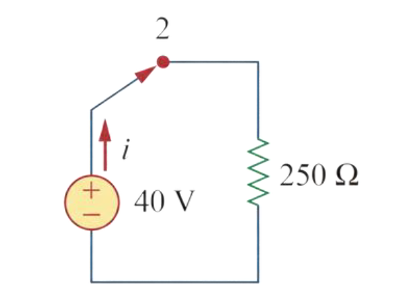
Figure 4 - Circuit diagram for solving the Pb-4 (when the switch is in position 2)
\small \begin{aligned} \therefore i = \frac{40}{250} = 0.16 \ A \end{aligned}
Solved Problems on Nodes, Branches, and Loops
In this section, we focus on the
Problem 5
Pb-5: For the network graph in Fig. 5, find the number of nodes, branches, and loops.

Figure 5 - Circuit diagram for Pb-5
Solution:

Figure 6 - Circuit diagram for solving the Pb-5
\small \begin{aligned} &\text{From the Fig. 6,} \\[2ex] &\quad \quad \text{Nodes, } n = 9 \\[2ex] &\quad \quad \text{Loops, } l = 7 \\[2ex] &\text{We know,} \\[2ex] &\quad b = n + l - 1 \\[2ex] &\quad \Rightarrow b = 9 + 7 - 1 \ \therefore b = 15 \end{aligned}
Problem 6
Pb-6: In the network graph shown in Fig. 7, determine the number of branches and nodes.
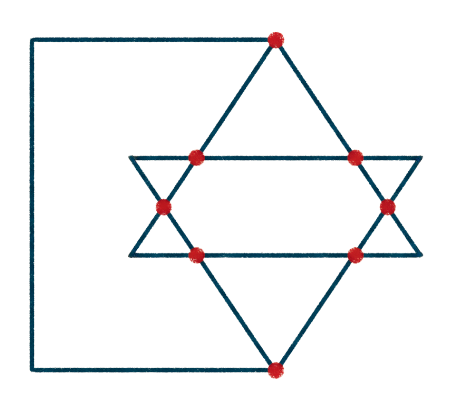
Figure 7 - Circuit diagram for Pb-6
Solution:
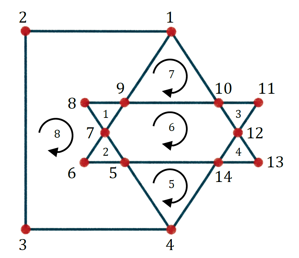
Figure 8 - Circuit diagram for solving the Pb-6
\small \begin{aligned} &\text{From the Fig. 8,} \\[2ex] &\quad \quad \text{Nodes, } n = 14 \\[2ex] &\quad \quad \text{Loops, } l = 8 \\[2ex] &\text{We know,} \\[2ex] &\quad b = n + l - 1 \\[2ex] &\quad \Rightarrow b = 14 + 8 - 1 \ \therefore b = 21 \end{aligned}
Problem 7
Pb-7: Determine the number of branches and nodes in the circuit of Fig. 9.

Figure 9 - Circuit diagram for Pb-7
Solution:

Figure 10 - Circuit diagram for solving the Pb-7
\small \begin{aligned} &\text{From the Fig. 10,} \\[2ex] &\quad \quad \text{Nodes, } n = 4 \\[2ex] &\quad \quad \text{Branches, } b = 6 \end{aligned}
Solved Problems on Kirchhoff’s Law
In this section, we focus on the
Problem 8
Pb-8: Design a problem, complete with a solution, to help students to better understand Kirchhoff’s Current Law. Design the problem by specifying values of i_a , i_b , and i_c , shown in in Fig. 11, and asking them to solve for values of i_1 , i_2 , and i_3 . Be careful to specify realistic currents.
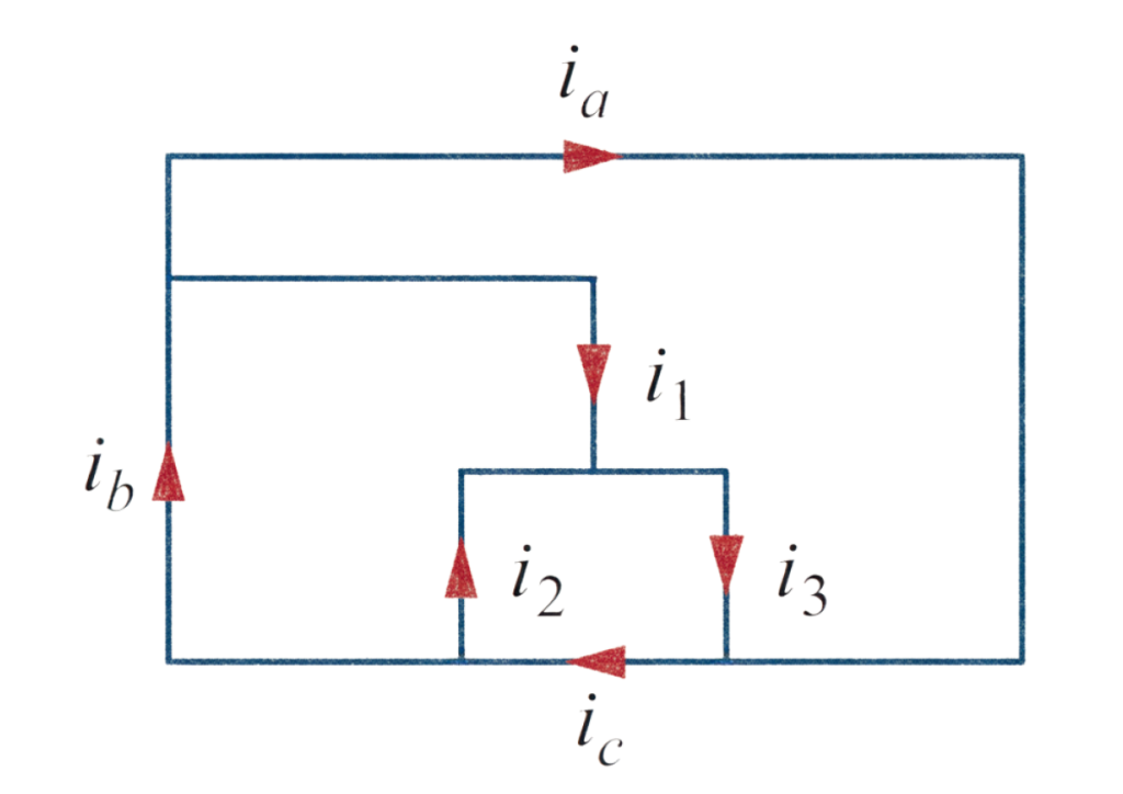
Figure 11 - Circuit diagram for Pb-8
Solution:

Figure 12 - Circuit diagram for solving the Pb-8
Determine i_1 , i_2 , and i_3 in the circuit of Fig. 12.
\small \begin{aligned} &\text{Applying Kirchhoff's Current Law in Fig 12:} \\[2ex] &\text{KCL at node a,} \\[2ex] &\quad i_b - i_a - i_1 = 0 \Rightarrow 8 - 3 - i_1 = 0 \\[2ex] &\quad \therefore i_1 = 5 \ A \\[2ex] &\text{KCL at node b,} \\[2ex] &\quad -i_b - i_2 + i_c = 0 \Rightarrow -8 - i_2 + 14 = 0 \\[2ex] &\quad \therefore i_2 = 6 \ A \\[2ex] &\text{KCL at node c,} \\[2ex] &\quad i_a + i_3 - i_c = 0 \Rightarrow 3 + i_3 - 14 = 0 \\[2ex] &\quad \therefore i_3 = 11 \ A \end{aligned}
Problem 9
Pb-9: Find i_1 , i_2 , and i_3 in Fig. 13.
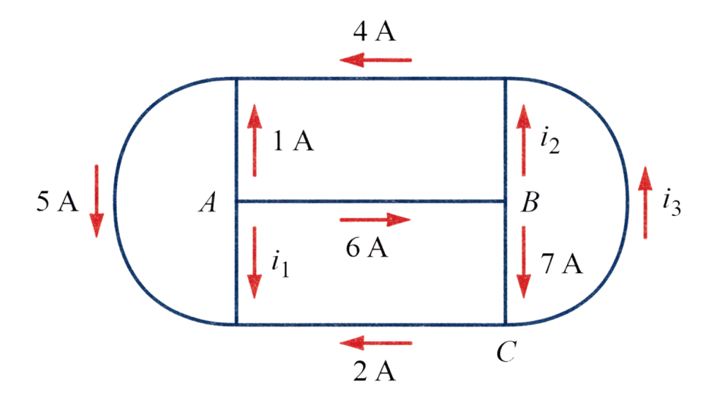
Figure 13 - Circuit diagram for Pb-9
Solution:
\small \begin{aligned} &\text{KCL at node A,} \\[2ex] &\quad -i_1 - 1 - 6 = 0 \therefore i_1 = -7 \ A \\[2ex] &\text{KCL at node B,} \\[2ex] &\quad 6 - i_2 - 7 = 0 \therefore i_2 = -1 \ A \\[2ex] &\text{KCL at node C,} \\[2ex] &\quad -2 + 7 - i_3 = 0 \therefore i_3 = 5 \ A \end{aligned}
Problem 10
Pb-10: Determine i_1 and i_2 in the circuit of Fig. 14.
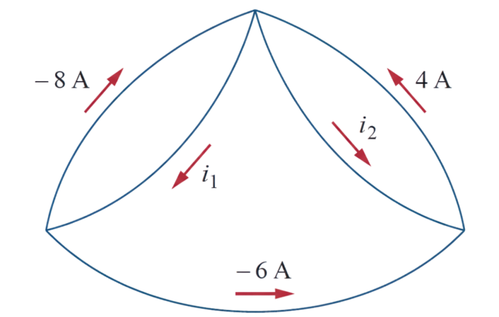
Figure 14 - Circuit diagram for Pb-10
Solution:
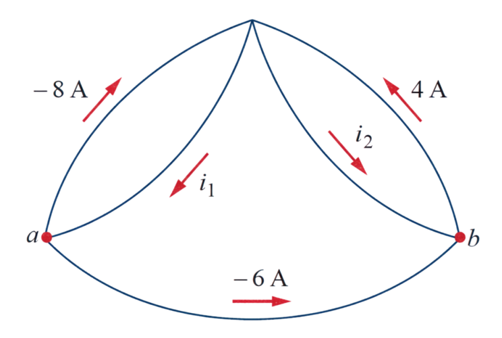
Figure 15 - Circuit diagram for solving the Pb-10
\small \begin{aligned} &\text{KCL at node a,} \\[2ex] &\quad i_1 - (-8) - (-6) = 0 \therefore i_1 = -14 \ A \\[2ex] &\text{KCL at node b,} \\[2ex] &\quad i_2 - 4 + (-6) = 0 \therefore i_2 = 10 \ A \end{aligned}
Problem 11
Pb-11: In the circuit of Fig. 16, calculate V_1 and V_2 .

Figure 16 - Circuit diagram for Pb-11
Solution:

Figure 17 - Circuit diagram for solving the Pb-11
\small \begin{aligned} &\text{KVL at loop 1,} \\[2ex] &\quad -V_1 + 1 + 5 = 0 \therefore V_1 = 6 \ V \\[2ex] &\text{KVL at loop 2,} \\[2ex] &\quad -5 + 2 + V_2 = 0 \therefore V_2 = 3 \ V \end{aligned}
Problem 12
Pb-12: In the circuit of Fig. 18, obtain v_1 , v_2 , and v_3 .

Figure 18 - Circuit diagram for Pb-12
Solution:
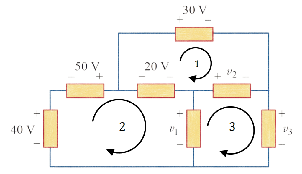
Figure 19 - Circuit diagram for solving the Pb-12
\small \begin{aligned} &\text{KVL at loop 1,} \\[2ex] &\quad -20 + 30 - v_2 = 0 \therefore v_2 = 10 \ V \\[2ex] &\text{KVL at loop 2,} \\[2ex] &\quad -40 - 50 + 20 + v_1 = 0 \therefore v_1 = 70 \ V \\[2ex] &\text{KVL at loop 3,} \\[2ex] &\quad -v_1 + v_2 + v_3 = 0 \Rightarrow -70 + 10 + v_3 = 0 \\[2ex] &\quad \therefore v_3 = 60 \ V \end{aligned}
Problem 13
Pb-13: For the circuit in Fig. 20, use KCL to find the branch currents I_1 to I_4 .
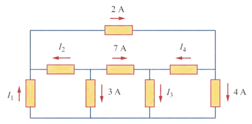
Figure 20 - Circuit diagram for Pb-13
Solution:

Figure 21 - Circuit diagram for solving the Pb-13
\small \begin{aligned} &\text{KCL at node b,} \\[2ex] &\quad -I_2 - 7 - 3 = 0 \therefore I_2 = -10 \ A \\[2ex] &\text{KCL at node a,} \\[2ex] &\quad I_1 + I_2 - 2 = 0 \Rightarrow I_1 - 10 - 2 = 0 \therefore I_1 = 12 \ A \\[2ex] &\text{KCL at node d,} \\[2ex] &\quad 2 - I_4 - 4 = 0 \therefore I_4 = -2 \ A \\[2ex] &\text{KCL at node c,} \\[2ex] &\quad 7 + I_4 - I_3 = 0 \Rightarrow 7 - 2 - I_3 = 0 \therefore I_3 = 5 \ A \end{aligned}
Problem 14
Pb-14: Given the circuit in Fig. 22, use KVL to find branch voltages V_1 to V_4 .
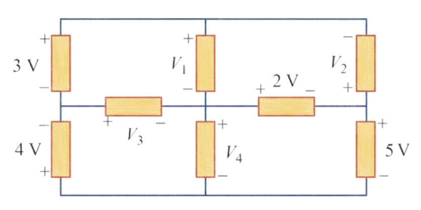
Figure 22 - Circuit diagram for Pb-14
Solution:
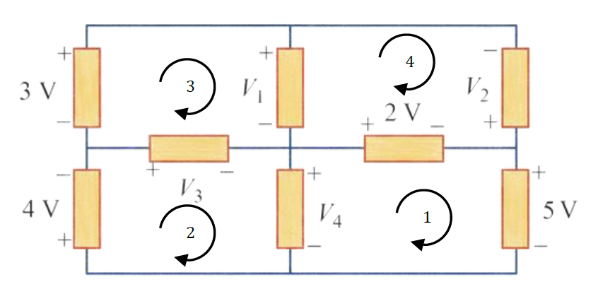
Figure 23 - Circuit diagram for solving the Pb-14
\small \begin{aligned} &\text{KVL at loop 1,} \\[2ex] &\quad -V_4 + 2 + 5 = 0 \therefore V_4 = 7 \ V \\[2ex] &\text{KVL at loop 2,} \\[2ex] &\quad 4 + V_3 + V_4 = 0 \Rightarrow 4 + V_3 + 7 = 0 \\[2ex] &\quad \therefore V_3 = -11V \\[2ex] &\text{KVL at loop 3,} \\[2ex] &\quad -3 + V_1 - V_3 = 0 \Rightarrow -3 + V_1 - (-11) = 0 \\[2ex] &\quad \therefore V_1 = -8 \ V \\[2ex] &\text{KVL at loop 4,} \\[2ex] &\quad -V_1 - V_2 - 2 = 0 \Rightarrow -(-8) - V_2 - 2 = 0 \\[2ex] &\quad \therefore V_2 = 6 \ V \end{aligned}
Problem 15
Pb-15: Calculate v and i_x in the circuit of Fig. 24.
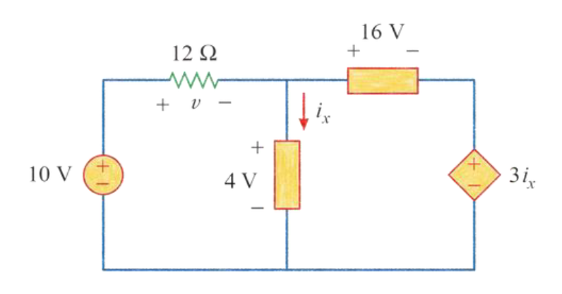
Figure 24 - Circuit diagram for Pb-15
Solution:
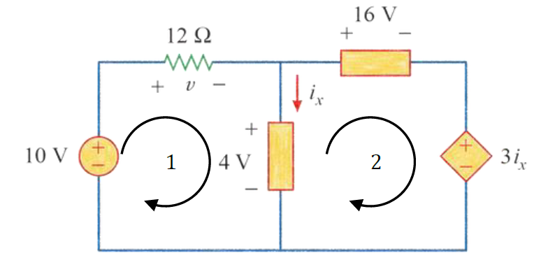
Figure 25 - Circuit diagram for solving the Pb-15
\small \begin{aligned} &\text{KVL at loop 1,} \\[2ex] &\quad -10 + v + 4 = 0 \therefore v = 6 \ V \\[2ex] &\text{KVL at loop 2,} \\[2ex] &\quad -4 + 16 + 3i_x = 0 \Rightarrow 3i_x = -12 \therefore i_x = -4 \ A \end{aligned}
Problem 16
Pb-16: Determine V_0 in the circuit of Fig. 26.
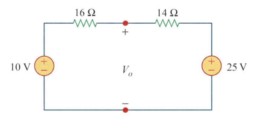
Figure 26 - Circuit diagram for Pb-16
Solution:
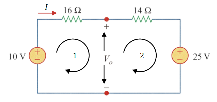
Figure 27 - Circuit diagram for solving the Pb-16
\small \begin{aligned} &\text{KVL at the outer loop,} \\[2ex] &\quad -10 + 16I + 14I + 25 = 0 \Rightarrow 30I + 15 = 0 \\[2ex] &\quad \therefore I = -\frac{1}{2} \ A \\[2ex] &\text{KVL at loop 1,} \\[2ex] &\quad -10 + 16I + V_0 = 0 \\[2ex] &\quad \Rightarrow -10 + 16 \cdot \left(-\frac{1}{2}\right) + V_0 = 0 \\[2.5ex] &\quad \Rightarrow -10 - 8 + V_0 = 0 \\[2ex] &\quad \therefore V_0 = 18 \ V \end{aligned}
Problem 17
Pb-17: Obtain v_1 through v_3 in the circuit of Fig. 28.
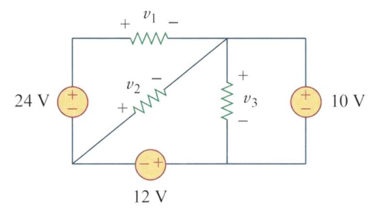
Figure 28 - Circuit diagram for Pb-17
Solution:

Figure 29 - Circuit diagram for solving the Pb-17
\small \begin{aligned} &\text{KVL at loop 1,} \\[2ex] &\quad -v_3 + 10 = 0 \therefore v_3 = 10 \ V \\[2ex] &\text{KVL at loop 2,} \\[2ex] &\quad 12 + v_2 + v_3 = 0 \\[2ex] &\quad \Rightarrow 12 + v_2 + 10 = 0 \\[2ex] &\quad \therefore v_2 = -22 \ V \\[2ex] &\text{KVL at loop 3,} \\[2ex] &\quad -24 + v_1 - v_2 = 0 \\[2ex] &\quad \Rightarrow -24 + v_1 - (-22) = 0 \\[2ex] &\quad \therefore v_1 = 2 \ V \end{aligned}
Problem 18
Pb-18: Find I and V_{ab} in the circuit of Fig. 30.
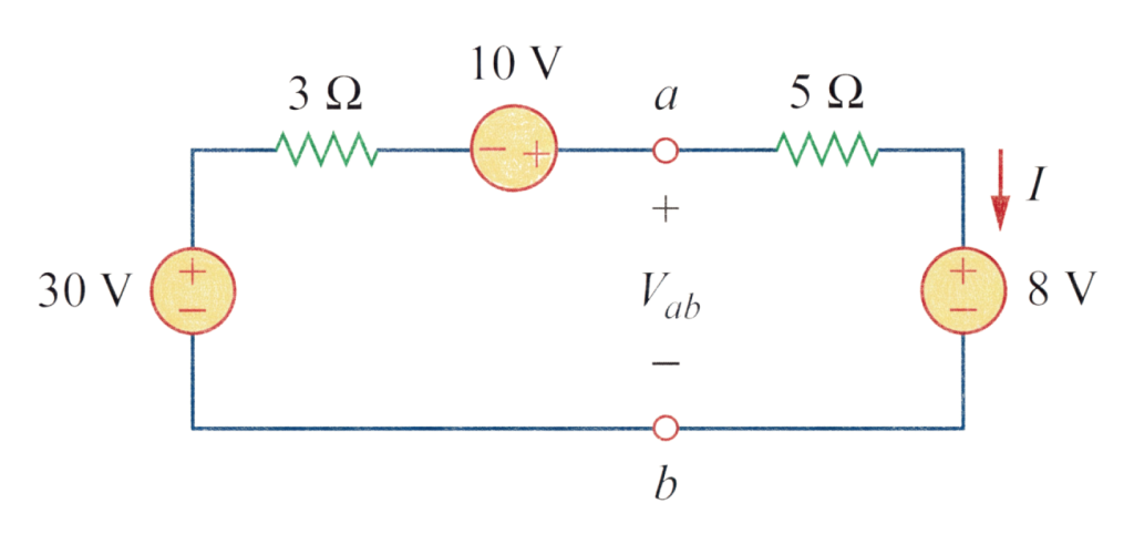
Figure 30 - Circuit diagram for Pb-18
Solution:

Figure 31 - Circuit diagram for solving the Pb-18
\small \begin{aligned} &\text{KVL at the outer loop,} \\[2ex] &\quad -30 + 3I - 10 + 5I + 8 = 0 \\[2ex] &\quad \Rightarrow 8I - 32 = 0 \\[2ex] &\quad \therefore I = 4 \ A \\[2ex] &\text{KVL at loop 2,} \\[2ex] &\quad -V_{ab} + 5I + 8 = 0 \\[2ex] &\quad \Rightarrow -V_{ab} + 5 \cdot 4 + 8 = 0 \\[2ex] &\quad \therefore V_{ab} = 28 \ V \end{aligned}
Problem 19
Pb-19: From the circuit in Fig. 32, find I , the power dissipated by the resistor, and the power supplied by each source.

Figure 32 - Circuit diagram for Pb-19
Solution:
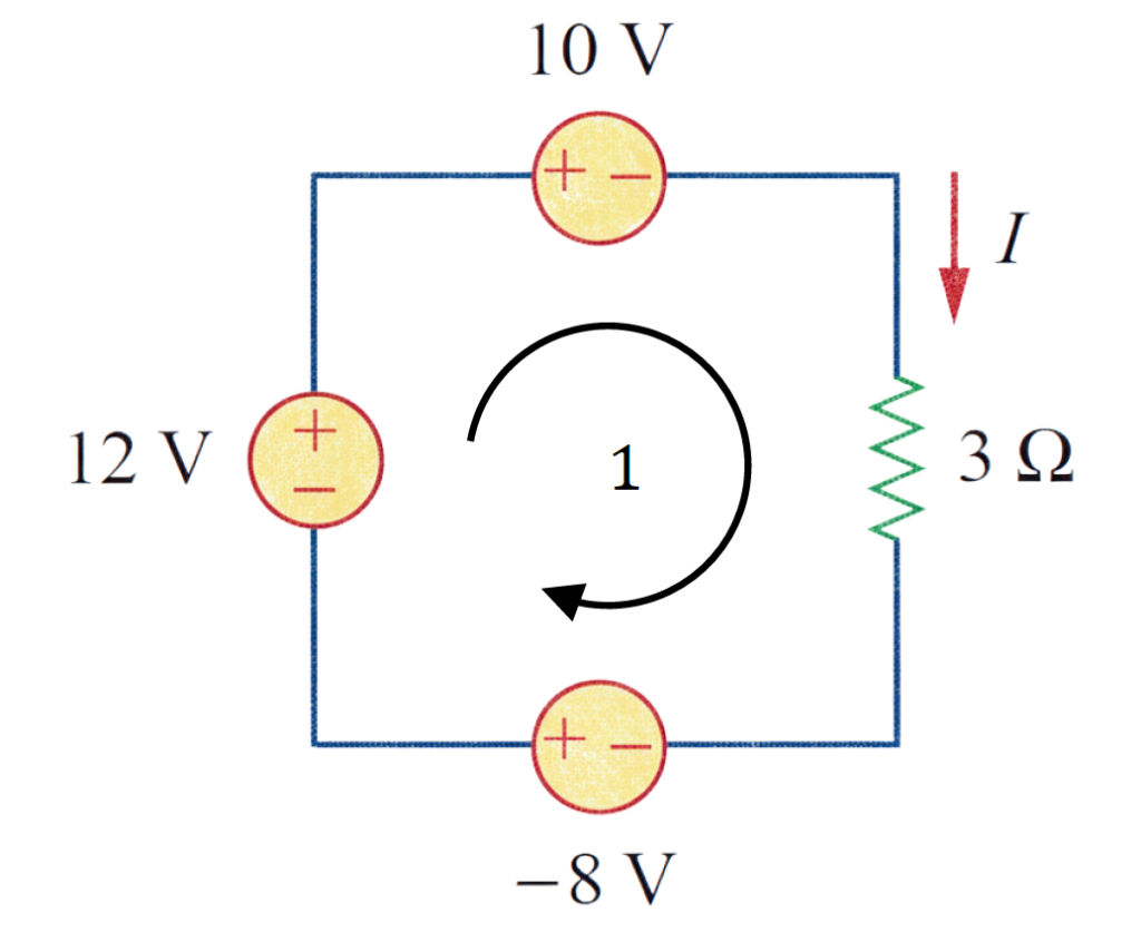
Figure 33 - Circuit diagram for solving the Pb-19
\small \begin{aligned} &\text{KVL at loop 1,} \\[2ex] &\quad -(-8) - 12 + 10 + 3I = 0 \\[2ex] &\quad \Rightarrow 3I + 6 = 0 \\[2ex] &\quad \therefore I = -2 \ A \\[2ex] &\therefore P_{3\Omega} = I^2R = (-2)^2 \times 3 = 12 \ W \\[2ex] &\therefore P_{12V} = 12 \times I = 12 \times (-2) = -24 \ W \\[2ex] &\therefore P_{10V} = -(10 \times I) = -{10 \times (-2)} = 20 \ W \\[2ex] &\therefore P_{-8V} = (-8) \times I = (-8) \times (-2) = 16 \ W \end{aligned}
Problem 20
Pb-20: Determine i_0 in the circuit of Fig. 34.
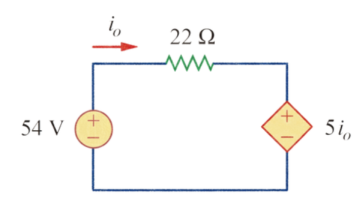
Figure 34 - Circuit diagram for Pb-20
Solution:

Figure 35 - Circuit diagram for solving the Pb-20
\small \begin{aligned} &\text{KVL at loop 1,} \\[2ex] &\quad -54 + 22i_0 + 5i_0 = 0 \\[2ex] &\quad \Rightarrow 27i_0 = 54 \\[2ex] &\quad \therefore i_0 = 2 \ A \end{aligned}
Problem 21
Pb-21: Find V_x in the circuit of Fig. 36.

Figure 36 - Circuit diagram for Pb-21
Solution:

Figure 37 - Circuit diagram for solving the Pb-21
\small \begin{aligned} &\text{KVL at loop 1,} \\[2ex] & -15 + I + 2V_x + 5I + 2I = 0 \\[2ex] & \Rightarrow -15 + I + 2 \cdot (5I) + 5I + 2I = 0 \ [\because V_x = 5I] \\[2ex] & \Rightarrow 18I - 15 = 0 \Rightarrow 18I = 15 \Rightarrow I = \frac{15}{18} \\[2ex] & \therefore I = \frac{5}{6} \ A \\[2ex] &\therefore V_x = 5I = 5 \times \frac{5}{6} = \frac{25}{6} = 4.17 \ V \end{aligned}
Problem 22
Pb-22: Find V_0 in the circuit of Fig. 38 and the power absorbed by the dependent source.
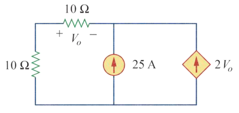
Figure 38 - Circuit diagram for Pb-22
Solution:
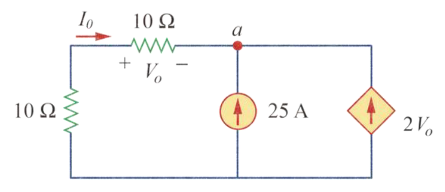
Figure 39 - Circuit diagram for solving the Pb-22
\small \begin{aligned} &\text{KCL at node a,} \\[2ex] &\quad I_0 + 25 + 2V_0 = 0 \Rightarrow \frac{V_0}{10} + 25 + 2V_0 = 0 \\[2ex] &\quad \therefore V_0 = -11.90 \ V \\[2ex] &\text{The current through the dependent source:} \\[2ex] &I = 2V_0 = 2 \times (-11.90) = -23.8 \ A \\[2ex] &\text{The voltage across the dependent source:} \\[2ex] &V = (10 + 10)I_0 = 20 \times \frac{V_0}{10} = 2V_0 = -23.8 \ V \\[2ex] &\therefore \text{ The power absorbed by the dependent} \\[0.5ex] &\text{source: } \\[2ex] & P = VI = (-23.8) \times (-23.8) = 566.44 \ W \end{aligned}
Problem 23
Pb-23: In the circuit shown in Fig. 40, determine v_x and the power absorbed by the 6 \ \Omega resistor.
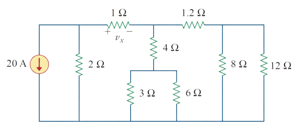
Figure 40 - Circuit diagram for Pb-23
Solution:
Simplifying the circuit,
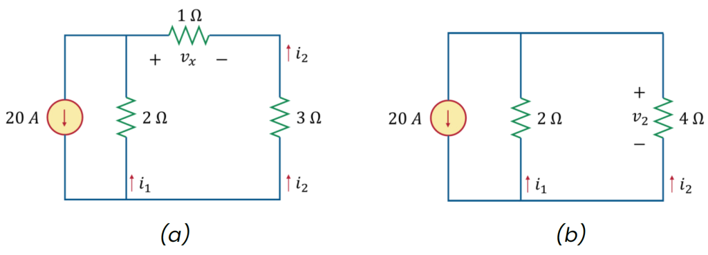
Figure 41 - Circuit diagram for solving the Pb-23 (for determining v_x )
\small \begin{aligned} &\text{Applying current division rule in Fig. 41 (b),} \\[2ex] &\quad i_2 = \frac{4||2}{4} \times 20 = \frac{(4^{-1}+2^{-1})^{-1}}{4} \times 20 \\[2ex] &\quad \therefore i_2 = 6.67 \ A \\[2ex] &\text{Now,} \\[2ex] &\quad \text{From Fig. 41 (b),} \\[2ex] &\quad \quad v_x = (-i_2) \times 1 = (-6.67) \times 1 \\[2ex] &\quad \quad \therefore v_x = -6.67 \ A \end{aligned}
From Fig. 41 (b), we get: i_2 = 6.67 \ A .
Now, simplifying the circuit in Fig. 40:

Figure 42 - Circuit diagram for solving the Pb-23 (for determining the power absorbed by the 6 \ \Omega resistor)
\small \begin{aligned} &\text{Applying current division rule in Fig. 42 (a),} \\[2ex] &\quad i_a = \frac{6||6}{6} \times (-i_2) = \frac{(6^{-1}+6^{-1})^{-1}}{6} \times (-6.67) \\[2ex] &\quad \therefore i_a = -3.335 \ A \\[2ex] &\text{Applying current division rule in Fig. 42 (b),} \\[2ex] &\quad i_{a6} = \frac{3||6}{6} \times i_a = \frac{(3^{-1}+6^{-1})^{-1}}{6} \times (-3.335) \\[2ex] &\quad \therefore i_{a6} = -1.112 \ A \\[2ex] &\text{The power absorbed by the } 6 \ \Omega \text{ resistor:} \\[2ex] &\quad p_{6\Omega} = (i_{a6})^2 \times 6 = (-1.112)^2 \times 6 \\[2ex] &\quad \therefore p_{6\Omega} = 7.42 \ W \end{aligned}
Problem 24
Pb-24: For the circuit in Fig. 43, find V_0/V_s in terms of \alpha , R_1 , R_2 , R_3 , and R_4 . If R_1 = R_2 = R_3= R_4 , what value of \alpha will produce | V_0/V_s |=10 ?
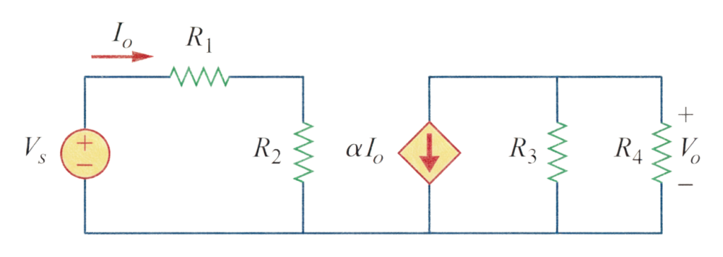
Figure 43 - Circuit diagram for Pb-24
Solution:
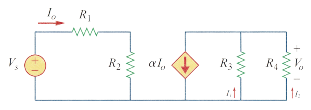
Figure 44 - Circuit diagram for solving the Pb-24
\small \begin{aligned} &\text{Using Ohm's Law,} \\[2ex] &\quad I_0 = \frac{V_s}{R_1+R_2} \\[2ex] &\text{Using current division rule,} \\[2ex] &\quad I_2 = \frac{R_3||R_4}{R_4} \times (\alpha I_0) = \frac{\frac{R_3 R_4}{R_3+R_4}}{R_4} \times (\alpha I_0) \\[2.5ex] &\quad \Rightarrow I_2 = \frac{R_3 R_4}{R_3+R_4} \times \frac{1}{R_4} \times (\alpha I_0) \\[2.5ex] &\quad \therefore I_2 = \frac{R_3}{R_3+R_4} \times (\alpha I_0) \\[2ex] &\text{Now,} \\[2ex] &\quad V_0 = -I_2 R_4 = -\frac{R_3}{R_3+R_4} \times (\alpha I_0) \\[2.5ex] &\quad \Rightarrow V_0 = -\frac{R_3 R_4}{R_3+R_4} \times \alpha \times \frac{V_s}{R_1+R_2} \\[2.5ex] &\quad \therefore \frac{V_0}{V_s} = -\frac{\alpha R_3 R_4}{(R_1+R_2)(R_3+R_4)} \\[2ex] &\text{Given,} \\[2ex] &\quad \left| \frac{V_0}{V_s} \right| = 10 \\[2.5ex] &\quad \Rightarrow \left| -\frac{\alpha R_3 R_4}{(R_1+R_2)(R_3+R_4)} \right| = 10 \\[2.5ex] &\quad \Rightarrow \frac{\alpha R^2}{4R^2} = 10 \\[2.5ex] &\quad \Rightarrow \frac{\alpha}{4} = 10 \\[2.5ex] &\quad \therefore \alpha = 40 \end{aligned}
Problem 25
Pb-25: For the circuit in Fig. 45, find the current, voltage and power associated with the 20 \ k \Omega resistor.
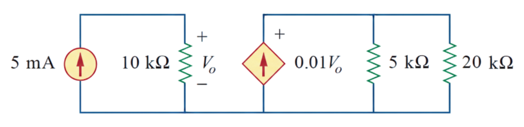
Figure 45 - Circuit diagram for Pb-25
Solution:
\small \begin{aligned} &\text{Using Ohm's Law,} \\[2ex] &\quad V_0 = (5 \times 10^{-3}) \times (10 \times 10^3) = 50 \ V \\[2ex] &\text{Using current division rule,} \\[2ex] &\quad I_{20k\Omega} = \frac{5||20}{20} \times 0.01V_0 \\[2.5ex] &\quad \Rightarrow I_{20k\Omega} = \frac{(5^{-1}+20^{-1})^{-1}}{20} \times 0.01 \times 50 \\[2ex] &\quad \therefore I_{20k\Omega} = 0.1 \ A \\[2ex] &V_{20k\Omega} = I_{20k\Omega} \times (20 \times 10^3) = 0.1 \times (20 \times 10^3) \\[2ex] &\therefore V_{20k\Omega} = 2000 \ V \\[2ex] &\therefore P_{20k\Omega} = V_{20k\Omega} \times I_{20k\Omega} = 2000 \times 0.1 = 200 \ W \end{aligned}
Solved Problems on Series and Parallel Resistors
In this section, we focus on the
Problem 26
Pb-26: For the circuit in Fig. 46, i_0 = 3 \ A . Calculate i_x and the total power absorbed by the entire circuit.
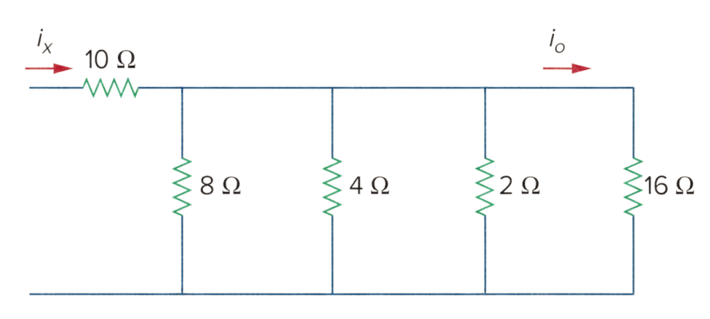
Figure 46 - Circuit diagram for Pb-26
Solution:
\small \begin{aligned} &R_{eq} = (8||4||2||16) + 10 \\[2ex] &\Rightarrow R_{eq} = (8^{-1} + 4^{-1} + 2^{-1} + 16^{-1})^{-1} + 10 \\[2ex] &\therefore R_{eq} = 11.07 \ \Omega \\[2ex] &\text{Using current division rule in Fig. 46,} \\[2ex] &\quad i_0 = \frac{(8||4||2||16)}{16} \times i_x \\[2ex] &\quad \Rightarrow 3 = \frac{(8^{-1}+4^{-1}+2^{-1}+16^{-1})^{-1}}{16} \times i_x \\[2ex] &\quad \therefore i_x = 45 \ A \\[2ex] &\text{The total power absorbed by the entire circuit:} \\[2ex] &\quad p_{total} = (i_x)^2 \times R_{eq} = (45)^2 \times 11.07 \\[2ex] &\quad \therefore p_{total} = 22416.75 \ W \end{aligned}
Problem 27
Pb-27: Calculate I_0 in the circuit of Fig. 47.
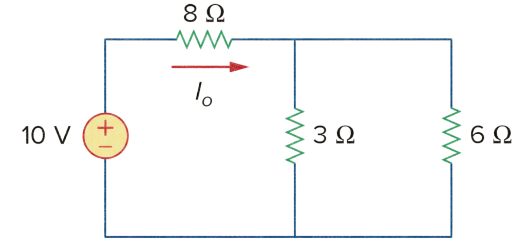
Figure 47 - Circuit diagram for Pb-27
Solution:
\small \begin{aligned} &R_{eq} = (3||6) + 8 = (3^{-1} + 6^{-1})^{-1} + 8 = 10 \ \Omega \\[2ex] &\therefore I_0 = \frac{10}{R_{eq}} = \frac{10}{10} = 1 \ A \end{aligned}
Problem 28
Pb-28: Design a problem, using Fig. 48, to help other students better understand series and parallel circuits.
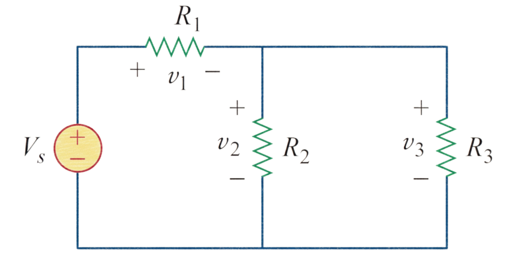
Figure 48 - Circuit diagram for Pb-28
Solution:
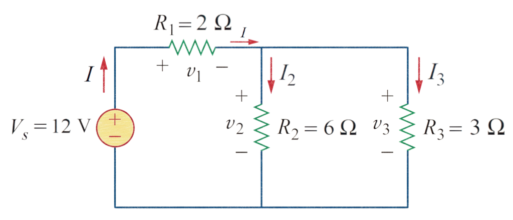
Figure 49 - Circuit diagram for solving the Pb-28
Find the total equivalent resistance, the total current, and v_1 , v_2 , and v_3 in the circuit of Fig. 49.
\small \begin{aligned} &\text{The total equivalent resistance:} \\[2ex] &\quad R_{eq} = (3||6) + 2 = (3^{-1} + 6^{-1})^{-1} + 2 = 4 \ \Omega \\[2ex] &\text{The total current:} \\[2ex] &\quad I = \frac{V_s}{R_{eq}} = \frac{12}{4} = 3 \ A \\[2ex] &\text{Using current division rule in Fig. 49,} \\[2ex] &\quad I_2 = \frac{(6||3)}{6} \times I = \frac{(6^{-1}+3^{-1})^{-1}}{6} \times 3 \\[2ex] &\quad \therefore I_2 = 1 \ A \\[2ex] &\quad \therefore I_3 = I - 1 = 3 - 1 = 2 \ A \\[2ex] &\therefore v_1 = IR_1 = 3 \times 2 = 6 \ V \\[2ex] &\therefore v_2 = I_2 R_2 = 1 \times 6 = 6 \ V \\[2ex] &\therefore v_3 = I_3 R_3 = 2 \times 3 = 6 \ V \end{aligned}
Problem 29
Pb-29: All resistors (R) in Fig. 50 are 5 \ \Omega each. Find R_{eq} .
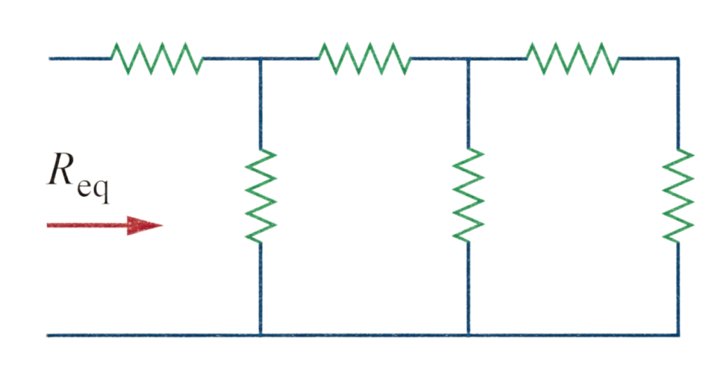
Figure 50 - Circuit diagram for Pb-29
Solution:
\small \begin{aligned} &R_{eq} = ((((5 + 5)||5) + 5)||5) + 5 \\[2ex] & \scriptsize {\Rightarrow R_{eq} = \left(\left(\left((5 + 5)^{-1} + 5^{-1}\right)^{-1} + 5\right)^{-1} + 5^{-1}\right)^{-1} + 5} \\[2ex] &\therefore R_{eq} = 8.125 \ \Omega \end{aligned}
Problem 30
Pb-30: Find R_{eq} for the circuit in Fig. 51.

Figure 51 - Circuit diagram for Pb-30
Solution:
\small \begin{aligned} &R_{eq} = ((180 + 60)||60) + 25 \\[2ex] &\Rightarrow R_{eq} = ((180 + 60)^{-1} + 60^{-1})^{-1} + 25 \\[2ex] &\therefore R_{eq} = 73 \ \Omega \end{aligned}
Problem 31
Pb-31: For the circuit in Fig. 52, determine i_1 to i_5 .
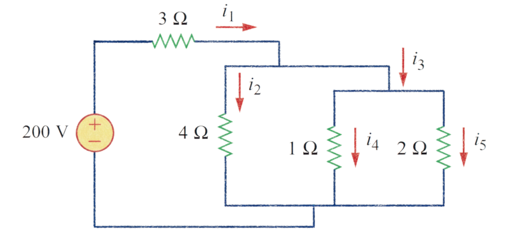
Figure 52 - Circuit diagram for Pb-31
Solution:
\small \begin{aligned} &R_{eq} = (4||1||2) + 3 \\[2ex] &\Rightarrow R_{eq} = (4^{-1} + 1^{-1} + 2^{-1})^{-1} + 3 \\[2ex] &\therefore R_{eq} = 3.57 \ \Omega \\[2.5ex] &\therefore i_1 = i_3 = \frac{200}{R_{eq}} = \frac{200}{3.57} = 56.02 \ A \\[2.5ex] &\text{Applying current division rule in Fig. 52,} \\[2.5ex] &i_2 = \frac{(4||1||2)}{4} \times i_1 = \frac{(4^{-1} + 1^{-1} + 2^{-1})^{-1}}{4} \times 56.02 \\[2.5ex] &\therefore i_2 = 7.98 \ A \\[2.5ex] &i_4 = \frac{(4||1||2)}{1} \times i_3 = \frac{(4^{-1} + 1^{-1} + 2^{-1})^{-1}}{1} \times 56.02 \\[2.5ex] &\therefore i_4 = 31.93 \ A \\[2.5ex] &i_5 = \frac{(4||1||2)}{2} \times i_3 = \frac{(4^{-1} + 1^{-1} + 2^{-1})^{-1}}{2} \times 56.02 \\[2.5ex] &\therefore i_5 = 15.97 \ A \end{aligned}
Problem 32
Pb-32: Find i_1 through i_4 in the circuit of Fig. 53.

Figure 53 - Circuit diagram for Pb-32
Solution:
Simplifying the circuit,
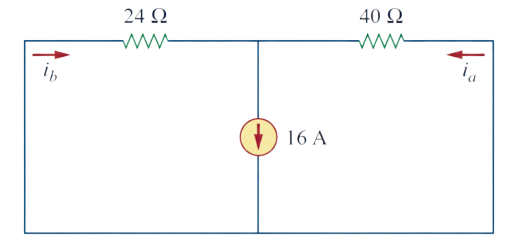
Figure 54 - Circuit diagram for solving the Pb-32
\small \begin{aligned} &\text{Applying current division rule in Fig. 54,} \\[2.5ex] &i_a = \frac{(24||40)}{40} \times 16 = \frac{(24^{-1}+40^{-1})^{-1}}{40} \times 16 \\[2.5ex] & \therefore i_a = 6 \ A \\[2.5ex] &i_b = \frac{(24||40)}{24} \times 16 = \frac{(24^{-1}+40^{-1})^{-1}}{24} \times 16 \\[2.5ex] & \therefore i_b = 10 \ A \end{aligned}
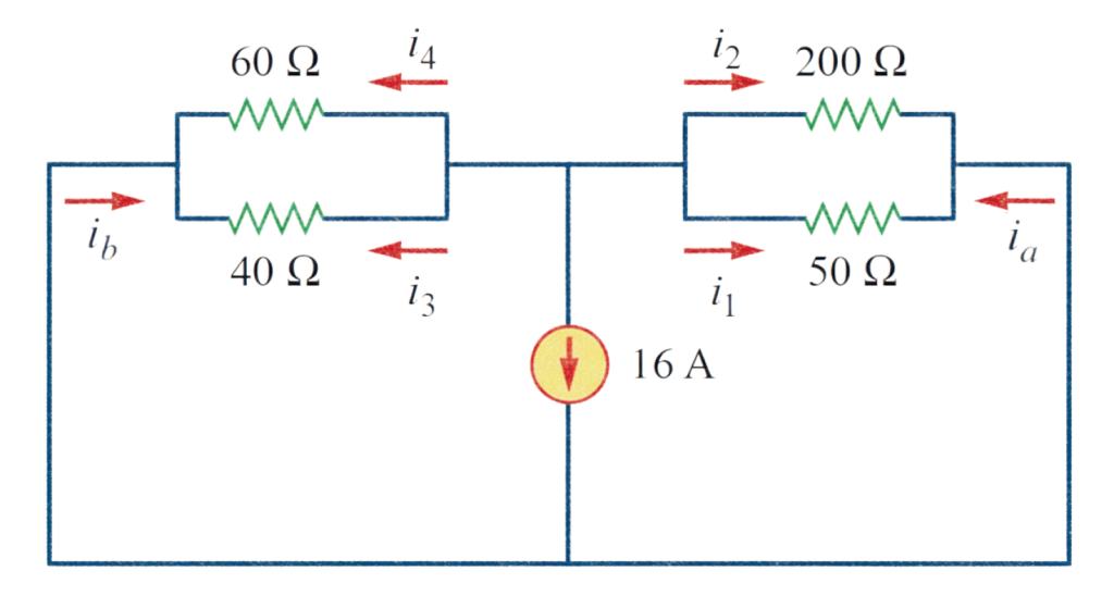
Figure 55 - Circuit diagram for solving the Pb-32 (for finding i_1 through i_4 )
\small \begin{aligned} &\text{Applying current division rule in Fig. 55,} \\[2.5ex] &i_1 = \frac{(200||50)}{50} \times (-i_a) \\[2.5ex] & \Rightarrow i_1 = \frac{(200^{-1}+50^{-1})^{-1}}{50} \times (-6) \\[2.5ex] & \therefore i_1 = -4.8 \ A \\[2.5ex] &i_2 = \frac{(200||50)}{200} \times (-i_a) \\[2.5ex] & \Rightarrow i_2 = \frac{(200^{-1}+50^{-1})^{-1}}{200} \times (-6) \\[2.5ex] & \therefore i_2 = -1.2 \ A \\[2.5ex] &i_3 = \frac{(60||40)}{40} \times (-i_b) \\[2.5ex] & \Rightarrow i_3 = \frac{(60^{-1}+40^{-1})^{-1}}{40} \times (-10) \\[2.5ex] & \therefore i_3 = -6 \ A \\[2.5ex] &i_4 = \frac{(60||40)}{60} \times (-i_b) \\[2.5ex] & \Rightarrow i_4 = \frac{(60^{-1}+40^{-1})^{-1}}{60} \times (-10) \\[2.5ex] & \therefore i_4 = -4 \ A \end{aligned}
Problem 33
Pb-33: Obtain v and i in the circuit of Fig. 56.
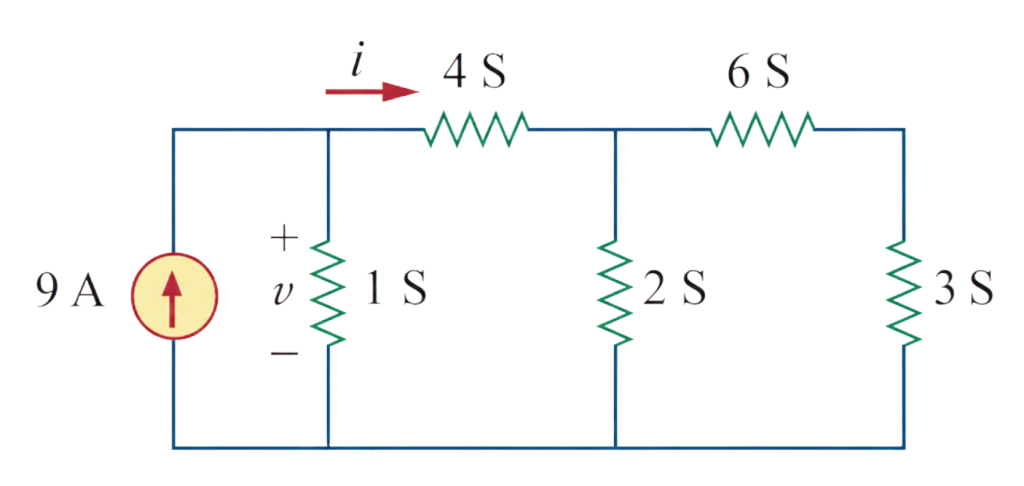
Figure 56 - Circuit diagram for Pb-33
Solution:
Simplifying the circuit in Fig. 56,

Figure 57 - Circuit diagram for solving the Pb-33
Converting the conductance to resistance in the circuit of Fig. 57 (b):

Figure 58 - Circuit diagram for solving the Pb-33 (for obtaining v and i )
\small \begin{aligned} &\text{Applying current division rule in Fig. 58,} \\[2.5ex] &i = \frac{1||0.5}{0.5} \times 9 = \frac{(1^{-1}+0.5^{-1})^{-1}}{0.5} \times 9 = 6 \ A \\[2.5ex] &\therefore i_1 = 9 - i = 9 - 6 = 3 \ A \\[2.5ex] &\therefore v = i_1 \times 1 = 3 \times 1 = 3 \ V \end{aligned}
Problem 34
Pb-34: Using series/parallel resistance combination, find the equivalent resistance seen by the source in the circuit of Fig. 59. Find the overall absorbed power by the resistor network.
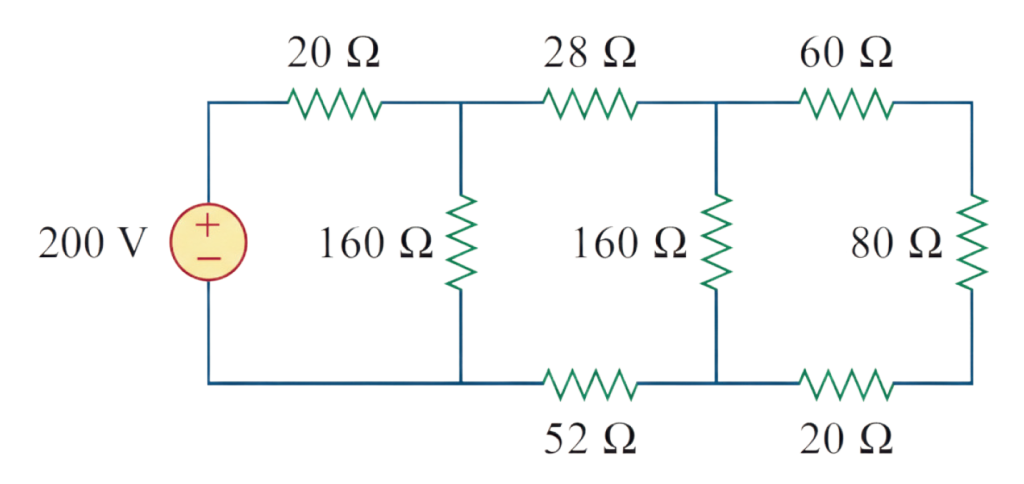
Figure 59 - Circuit diagram for Pb-34
Solution:
\small \begin{aligned} & \footnotesize{R_{eq} = (((((60 + 80 + 20)||160) + 28 + 52)||160) + 20} \\[2.5ex] & \scriptsize{\Rightarrow \mathrm{R}_{eq} = \left(\left(\left((60 + 80 + 20)^{-1} + 160^{-1}\right)^{-1} + 28 + 52\right)^{-1} + 160^{-1}\right)^{-1} + 20} \\[2.5ex] &\therefore R_{eq} = 100 \ \Omega \\[2.5ex] &\therefore p = 200 \times R_{eq} = 200 \times 100 = 20000 \ W \end{aligned}