

Mastering Circuits!
Mastering the concepts of noise in communication systems is essential for every student and aspiring engineer. In this comprehensive guide, we break down the fundamentals of noise, types of noise (like Thermal Noise, Shot Noise, Impulse Noise, Quantization Noise), Signal-to-Quantization-Noise Ratio (SQNR), noise figure, noise temperature. You will also explore the relationship between signal power and noise density, and learn about the equivalent noise figure and noise temperature in a cascaded communication system. Whether you are preparing for an exam or refreshing your knowledge, join Mastering Circuits as we solve practical problems to help you bridge the gap between theory and practice.
Introduction
Noise
Noise is random, undesirable electrical energy that enters the communication system via the medium and interferes with the transmitted message.
Some noise is produced in the receiver.
Noise gets added to the signal and degrades the quality of the signal.
Noise Vs. Interference
Although they play a somewhat similar role in electrical systems, they are dissimilar in nature in one important aspect.
- Noise is usually composed of randomly occuring voltages which are unrelated in phase or frequency and may sometimes be of a very peaky nature.
- Interference, on the other hand, is usually more structured than noise since it arises as unwanted coupling from just a few signals (e.g., from other users) in the network.
Sources of Noise
Primarily, there are two sources of noise. Ex:
- Artificial or Man-Made Sources:
- Commutator motors
- Spark plugs of vehicles
- Faulty switches
- Fluorescent lights
- Electric shavers
- Natural Sources:
- Cosmic radiation
- Atmospheric (e.g., lightning discharge, rain attenuation)
- Intrinsic circuit noise
Types of Noise
Primarily, there are four types of noise. Ex:
- Thermal Noise
- Shot Noise
- Impulse Noise
- Quantization Noise
- Thermal Noise: Thermal noise, also known as Johnson-Nyquist noise, is the most fundamental and unavoidable type of internal noise in electronic systems. It arises from the random thermal motion of free electrons within any conducting materials.
- At any temperature above absolute zero (0 \, K) , electrons in a conductor are in a state of constant, random motion. This chaotic movement of charge carriers creates small, unpredictable voltage fluctuations across the terminal of a resistor or conductor.
Noise Power Spectral Density (PSD)
Noise PSD represents noise power per unit bandwidth.
\small PSD = \frac{\textit{Noise Power}}{\textit{Bandwidth}}
White Noise
White noise means it contains noise of all frequency with a flat PSD.
- Thermal noise is considered ‘White’ because its PSD is flat acorss a very wide range of frequencies, meaning it contains equal power per unit of bandwidth.
- The intensity of the thermal noise is directly proportional to the absolute temperature of the conductor. As the temperature increases, the noise power increases.

Figure 1: Random motion of electrons in a conductor
The electrons in a conductor have kinetic energy and are in random motions, creating a randomly varying voltage across the ends of the conductor. This is how thermal noise is generated.
- The Average value of the randomly varying voltages is zero.
- The RMS (Root Mean Square) value of the randomly varying voltages is finite.

Figure 2: Circuit model of thermal noise voltage
\small \begin{aligned} & \text{The Mean Square Thermal Noise Voltage at the} \\[1ex] & \text{terminal of an open circuit resistor is given by:} \\[2.5ex] & \, \, \, \, \, \, \, \, \, \, \, \, \, \, (V_n)^2 = 4KTBR \\[2.5ex] & \, \, \, \, \, \, \, \, \, \, \, \, \, \, \therefore V_n = \sqrt{4KTBR} \\[2.5ex] & \text{Where,} \\[2.5ex] & \quad (V_n)^2 = \text{Mean square value of thermal noise} \\[1ex] & \text{ \, \, \, \, \, \, \, \, \, \, voltage} \\[2ex] & \quad V_n = \text{RMS (Root Mean Square) value of} \\[1ex] & \text{ \, \, \, \, \, \, \, \, thermal noise voltage} \\[2ex] & \quad K = \text{Boltzmann constant} \ (1.38 \times 10^{-23} \ \text{JK}^{-1}) \\[2ex] & \quad B = \text{Bandwidth} \ (\text{Hz}) \\[2ex] & \quad T = \text{Temperature} \ (\text{K}) \\[2ex] & \quad R = \text{Resistance} \ (\Omega) \end{aligned}
\small \text{Thermal Noise Power,} \, \, P_{n} = KTB

Figure 3: Circuit model of thermal noise current
\small \text{Thermal Noise Current,} \, \, I_{n} = \sqrt{\frac{4KTB}{R}}
- Shot Noise: Shot noise is a fundamental type of internal noise that arises from the discrete nature of electric current. While electric current is often viewed as a continuous flow, it actually consists of individual, quantized charge carriers (electrons and holes)
- Shot noise is produced when these discrete charge carriers randomly cross a potential barrier, sucha as a P-N junction in a diode or a transistor.
- A resistor normally does not produce shot noise since there is no potential barrier built within a resistor.
- A diode, a transistor, and vacuum tube all will produce shot noise.
- If the active device (diode, transistor) provides amplification, the noise also gets amplified along with the signal.
- Like thermal noise, shot noise is also characterized as ‘White’ because its PSD is flat across a very wide range of frequencies.
The intensity of shot noise is directly related to the average DC current flowing through the device. The mean square shot noise current (I_{sh}^{2}) is given by:
\small \begin{aligned} & \, \, \, \, \, \, \, \, \, \, \, \, \, \, I_{sh}^2 = 2qI_{DC}B \\[2.5ex] & \text{Where,} \\[2.5ex] & \quad q = \text{The electronic charge } (1.6 \times 10^{-19} \ C) \\[2ex] & \quad I_{DC} = \text{The average direct current (DC)} \\ & \quad \quad \quad \quad \text{flowing through the junction} \\[2ex] & \quad B = \text{Bandwidth of the system} \end{aligned}
- Impulse Noise: Impulse noise is a category of non continuous noise consisting of sudden, irregular bursts or spikes of high amplitude electrical energy with a very short duration. Unlike thermal or shot noise which are constant and predictable over time, impulse noise is unpredictable.
- The most common source of impulse noise is Switching Transients. Turning on or off heavy electrical machinery, motor, or even home appliances create sudden voltage spikes in power lines that couple with communication circuits.
- Quantization Noise: Quantization noise is a type of error introduced during the analog-to-digital conversion (ADC) process. It occurs when a continuous amplitude analog signal is mapped onto a finite set of discrete digital levels.
The Quantization Process
In digital system, an analog signal is sampled and then quantized. Because a digital system has a limited number of levels (L) which are determined by the number of bits (n) and L = 2^{n} , it can not perfectly represent every possible analog value. The quantizer must round the analog signal to the nearest available discrete level.
- Quantization Error \mathbf{(e)} : The difference between the actual analog sample value (x) and the discrete quantized value (\hat{x})
\small e = x - \hat{x}
- Step Size \mathbf{(\Delta)} : The distance between two adjacent quantization levels. If a signal have a range of [V_{max}, V_{min}] consisting the peak-to-peak voltage, V_{pp} = V_{max} - V_{min} and uses (L) levels, the step size is:
\small \Delta = \frac{V_{pp}}{L} = \frac{V_{max} - V_{min}}{2^{n}}
Mathematical Modeling of Noise
Quantization noise is often modeled as a random variable. For a uniform quantizer (where all steps are equal) and a signal that varies significantly across levels, the noise is assumed to be uniformly distributed between -\Delta/2 and +\Delta/2 .
- Mean square quantization noise \mathbf{(N_{q})} : This represents the ‘Noise Power’ and is calculated as:
\small N_q = \overline{e^2} = \frac{\Delta^2}{12}
The RMS value of quantization noise voltage is given by:
\small (V_q)_{rms} = \sqrt{\overline{e^2}} = \sqrt{\frac{\Delta^2}{12}}
Signal-to-Quantization Noise Ratio (SQNR)
The SQNR is the primary matric used to measure the quality of a digitalized signal. It is the ratio of the signal power (P_{s}) to the quantization noise power (N_{q}) .
\small SQNR = \frac{Signal \ Power}{Quantization \ Noise \ Power} = \frac{P_{s}}{N_{q}}
For a sinusoidal signal using an n-bit quantizer, the SQNR can be simplified as:
\small SQNR_{dB} \approx 6.02n + 1.76 \ dB
\small \begin{aligned} & \textbf{For the quantization noise,} \\[2.5ex] & \quad \text{Step Size, } \Delta = \frac{V_{pp}}{L} = \frac{V_{max} - V_{min}}{2^{n}} \\[2.5ex] & \quad \text{Noise Power, } P_{q} = \frac{\Delta^{2}}{12} \\[2.5ex] & \quad \text{RMS value of quantization noise} \\[1ex] & \quad \text{voltage, } (V_{q})_{rms} = \sqrt{\frac{\Delta^{2}}{12}} \\[2.5ex] & \quad SQNR_{dB} = 6.02n + 1.76 \ dB \end{aligned}
Solved Problems on Types of Noise
Problem 1
Pb-1: What is noise? What are the sources of noise in communication system?
Solution:
Noise: Noise is random, undesirable electrical energy that enters the communication system via the medium and interferes with the transmitted message.
Primarily, there are two sources of noise. Ex:
- Artificial or Man-Made Sources:
- Commutator motors
- Spark plugs of vehicles
- Faulty switches
- Fluorescent lights
- Electric shavers
- Natural Sources:
- Cosmic radiation
- Atmospheric (e.g., lightning discharge, rain attenuation)
- Intrinsic circuit noise
Problem 2
Pb-2: Thermal noise characteristic is White – Explain it.
Solution:
White noise means it contains noise of all frequency with a flat PSD. Thermal noise is considered ‘White’ because its PSD is flat across a very wide range of frequencies, meaning it contains equal power per unit of bandwidth.
Problem 3
Pb-3: Bandwidth = 4 \, kHz , Signal Power = 0.1 \, mW , Noise PSD, \sigma^2 = 10^{-12} \, W/Hz . Capacity = ?
Solution:
\small \begin{aligned} &\text{Here,} \\[2.5ex] & \quad \text{Bandwidth, } B = 4 \ kHz = 4000 \ Hz \\[2.5ex] & \quad \text{Signal Power, } S = 0.1 \ mW = 10^{-4} \ W \\[2.5ex] & \quad \text{Noise PSD, } \sigma^2 = 10^{-12} \ W/Hz \\[2.5ex] & \quad \Rightarrow \frac{\textit{Noise Power}}{\textit{Bandwidth}} = 10^{-12} \\[2.5ex] & \quad \Rightarrow \frac{N}{B} = 10^{-12} \Rightarrow \frac{N}{4000} = 10^{-12} \\[2.5ex] & \quad \therefore N = 4 \times 10^{-9} \ W \\[2.5ex] &\text{We know,} \\[2.5ex] & \quad C = B \log_{2} \left( 1 + \frac{S}{N} \right) \\[2.5ex] & \quad \quad = 4000 \times \log_{2} \left( 1 + \frac{10^{-4}}{4 \times 10^{-9}} \right) \\[2.5ex] & \quad \quad = 58438.79 \ bps \end{aligned}
Problem 4
Pb-4: A 10 \, k\Omega resistor is at a room temperature of 27^\circ \, C . Calculate the available noise power and the rms noise voltage for a bandwidth of 1 \, MHz . ( The Boltzmann constant, 1.38 \times 10^{-23} \, JK^{-1})
Solution:
\small \begin{aligned} &\text{Here,} \\[2ex] & \quad R = 10 \ k\Omega = 10^4 \ \Omega \\[2ex] & \quad T = 27^\circ \ C = (27 + 273) \ K = 300 \ K \\[2ex] & \quad B = 1 \ MHz = 10^6 \ Hz \\[2ex] & \quad K = 1.38 \times 10^{-23} \ JK^{-1} \\[3ex] &\text{We know,} \\[2.5ex] & \quad \text{Noise Power, } P_n = KTB \\[2ex] & \quad \phantom{\text{Noise Power, } P_n} = (1.38 \times 10^{-23}) \times 300 \times 10^6 \\[2ex] & \quad \phantom{\text{Noise Power, } P_n} = 4.14 \times 10^{-15} \ W \\[3ex] &\text{Now,} \\[2.5ex] & \quad V_n = \sqrt{4KTBR} \\[2ex] & \quad \phantom{V_n} = \sqrt{4 \times 1.38 \times 10^{-23} \times 300 \times 10^6 \times 10^4} \\[2ex] & \quad \phantom{V_n} = 1.29 \times 10^{-5} \ V \end{aligned}
Problem 5
Pb-5: A communication receiver operates at a temperature of 290 \, K with a bandwidth of 10 \, MHz . The received signal power is -90 \, dBm . Calculate the available thermal noise power in watts and dBm, and determine the SNR at the receiver input in decibels (dB) .
Solution:
\small \begin{aligned} &\text{Here,} \\[2ex] & \quad T = 290 \ K \\[2ex] & \quad B = 10 \ MHz = 10^{7} \ Hz \\[2ex] & \quad K = 1.38 \times 10^{-23} \ JK^{-1} \\[3ex] &\text{We know,} \\[2.5ex] & \quad P_{n} = KTB \\[2ex] & \quad \Rightarrow P_{n} = 1.38 \times 10^{-23} \times 290 \times 10^{7} \\[2ex] & \quad \Rightarrow (P_{n})_{W} = 4.002 \times 10^{-14} \ W \\[2ex] & \quad \Rightarrow (P_{n})_{mW} = 4.002 \times 10^{-14} \times 10^{3} \ mW \\[2ex] & \quad \Rightarrow (P_{n})_{dBm} = 10 \log_{10}(4.002 \times 10^{-11}) \\[2ex] & \quad \therefore (P_{n})_{dBm} = -103.98 \ dBm \\[3ex] &\text{Now,} \\[2.5ex] & \quad \text{Signal power, } (P_{s})_{dBm} = -90 \ dBm \\[2ex] & \quad \text{Noise power, } (P_{n})_{dBm} = -103.98 \ dBm \\[2ex] & \quad \therefore SNR_{dB} = (P_{s})_{dBm} - (P_{n})_{dBm} \\[2ex] & \quad \phantom{\therefore SNR_{dB}} = -90 - (-103.98) \\[2ex] & \quad \phantom{\therefore SNR_{dB}} = 13.98 \ dB \end{aligned}
Problem 6
Pb-6: A sensor produces a signal voltage of 80 \, \mu V across a 10 \, k\Omega load resistor. The entire circuit operates at a temperature of 27^\circ \, C with a measurement bandwidth of 5 \, MHz . Calculate the RMS thermal noise voltage generated by the resistor and determine the SNR in decibels (dB) .
Solution:
\small \begin{aligned} &\text{Here,} \\[2ex] & \quad R = 10 \ k\Omega = 10^4 \ \Omega \\[2ex] & \quad T = 27^\circ \ C = (27 + 273) \ K = 300 \ K \\[2ex] & \quad B = 5 \ MHz = 5 \times 10^6 \ Hz \\[2ex] & \quad K = 1.38 \times 10^{-23} \ JK^{-1} \\[3ex] &\text{We know,} \\[2.5ex] & \quad V_n = \sqrt{4KTBR} \\[2ex] & \quad \phantom{V_n} = \sqrt{4 \times 1.38 \times 10^{-23} \times 300 \times 5 \times 10^6 \times 10^4} \\[2ex] & \quad \phantom{V_n} = 2.88 \times 10^{-5} \ V \\[3ex] &\text{Now,} \\[2.5ex] & \quad \text{Signal voltage, } V_s = 80 \ \mu V = 80 \times 10^{-6} \ V \\[2ex] & \quad \text{Noise voltage, } V_n = 2.88 \times 10^{-5} \ V \\[2ex] & \quad \therefore SNR_{dB} = 20 \log_{10} \left( \frac{V_s}{V_n} \right) \\[2ex] & \quad \phantom{\therefore SNR_{dB}} = 20 \times \log_{10} \left( \frac{80 \times 10^{-6}}{2.88 \times 10^{-5}} \right) \\[2ex] & \quad \phantom{\therefore SNR_{dB}} = 8.87 \ dB \end{aligned}
Problem 7
Pb-7: Pressure is measured by strain gauges. One strain gauge is active and the other is dummy. These strain gauges form the opposite arms of a Wheatstone Bridge. The other two arms are formed by equal resistances of 120 \, \Omega each at 300 \, K . The frequency bandwidth is 100 \, kHz . The output of the bridge is a voltage signal. When a pressure of 7000 \, kN/m^{2} is applied, the output voltage is 0.12 \, mV . Find the SNR generated by the resistors. ( The Boltzmann constant, 1.38 \times 10^{-23} \, JK^{-1})
Solution:
\small \begin{aligned} &\text{Here,} \\[2ex] & \quad R = 120 \ \Omega \\[2ex] & \quad T = 300 \ K \\[2ex] & \quad B = 100 \ kHz = 10^5 \ Hz \\[2ex] & \quad K = 1.38 \times 10^{-23} \ JK^{-1} \\[3ex] &\text{We know,} \\[2.5ex] & \quad V_n = \sqrt{4KTBR} \\[2ex] & \quad \phantom{V_n} = \sqrt{4 \times 1.38 \times 10^{-23} \times 300 \times 10^5 \times 120} \\[2ex] & \quad \phantom{V_n} = 4.46 \times 10^{-7} \ V \\[3ex] &\text{Now,} \\[2.5ex] & \quad \text{Signal voltage, } V_s = 0.12 \ mV = 0.12 \times 10^{-3} \ V \\[2ex] & \quad \text{Noise voltage, } V_n = 4.46 \times 10^{-7} \ V \\[2ex] & \quad \therefore SNR_{dB} = 20 \log_{10} \left( \frac{V_s}{V_n} \right) \\[2ex] & \quad \phantom{\therefore SNR_{dB}} = 20 \times \log_{10} \left( \frac{0.12 \times 10^{-3}}{4.46 \times 10^{-7}} \right) \\[2ex] & \quad \phantom{\therefore SNR_{dB}} = 48.6 \ dB \end{aligned}
Problem 8
Pb-8: Calculate the signal-to-noise ratio in dB for a uniform quantization system with a signal range of [-5, 5] , average power of 3 watts, and 4 bits per level.
Solution:
\small \begin{aligned} &\text{Here,} \\[2ex] & \quad \text{Signal range } = [-5, 5] \ V \\[2ex] & \quad \therefore \text{Peak-to-peak voltage, } V_{pp} = V_{max} - V_{min} \\[2ex] & \quad \phantom{\therefore \text{Peak-to-peak voltage, } V_{pp}} = 5 - (-5) \ V \\[2ex] & \quad \phantom{\therefore \text{Peak-to-peak voltage, } V_{pp}} = 10 \ V \\[2ex] & \quad \text{Signal power, } P_s = 3 \ W \\[2ex] & \quad \text{Bit, } n = 4 \ \textit{bits} \\[2ex] & \quad \text{Levels, } L = 2^n = 2^4 = 16 \ \textit{levels} \\[3ex] &\text{We know,} \\[2.5ex] & \quad \text{Step size, } \Delta = \frac{V_{pp}}{L} = \frac{10}{16} = 0.625 \\[3ex] &\text{Now,} \\[2.5ex] & \quad \text{Quantization noise power, } P_q = \frac{\Delta^2}{12} \\[2ex] & \quad \phantom{\text{Quantization noise power, } P_q} = \frac{(0.625)^2}{12} \\[2ex] & \quad \phantom{\text{Quantization noise power, } P_q} = 0.0326 \ W \\[3ex] & \quad \therefore SNR_{dB} = 10 \log_{10} \left( \frac{P_s}{P_q} \right) \\[2ex] & \quad \phantom{\therefore SNR_{dB}} = 10 \times \log_{10} \left( \frac{3}{0.0326} \right) \\[2ex] & \quad \phantom{\therefore SNR_{dB}} = 19.64 \ dB \end{aligned}
Problem 9
Pb-9: Calculate the output signal-to-quantization noise ratio for a television signal transmitted using binary PCM with 512 levels.
Solution:
\small \begin{aligned} &\text{Here,} \\[2ex] & \quad L = 512 \\[2ex] & \quad \Rightarrow 2^n = 512 \\[2ex] & \quad \Rightarrow \log_{2}(2^n) = \log_{2}(512) \\[2ex] & \quad \Rightarrow n = \log_{2}(512) \\[2ex] & \quad \therefore n = 9 \\[3ex] &\text{We know,} \\[2.5ex] & \quad SQNR_{dB} = 6.02n + 1.76 \ dB \\[2ex] & \quad \phantom{SQNR_{dB}} = (6.02 \times 9) + 1.76 \ dB \\[2ex] & \quad \phantom{SQNR_{dB}} = 55.94 \ dB \end{aligned}
Problem 10
Pb-10: A sinusoidal signal is quantized using a uniform quantizer. If the required SQNR is at least 40 \, dB , determine the minimum number of bits (n) and the number of levels (L) .
Solution:
\small \begin{aligned} & SQNR_{dB} = 6.02n + 1.76 \geq 40 \\[2.5ex] & \, \, \, \, \, \, \, \, \, \, \, \, \, \, \, \, \, \, \, \, \, \, \, \, \, \, \, \, \, \, \, \Rightarrow 6.02n \geq 38.24 \\[2.5ex] & \, \, \, \, \, \, \, \, \, \, \, \, \, \, \, \, \, \, \, \, \, \, \, \, \, \, \, \, \, \, \, \therefore n \geq 6.35 \\[3ex] & \text{Since bits must be integer, therefore } n = 7 \ \textit{bits} \\[2.5ex] & \text{Number of levels, } L = 2^n = 2^7 = 128 \ \textit{levels} \end{aligned}
Problem 11
Pb-11: An analog signal is uniformly distributed between -5 \, V and +5 \, V . If the signal is quantized using 4 bits, calculate the step size, noise power, and SQNR ( with P_{s} = 3 \, W) .
Solution:
\small \begin{aligned} &\text{Here,} \\[2ex] & \quad V_{pp} = 5 - (-5) = 10 \ V \\[2ex] & \quad n = 4 \ \textit{bits} \\[2ex] & \quad P_s = 3 \ W \\[3ex] &\text{We know,} \\[2.5ex] & \quad \text{Step size, } \Delta = \frac{V_{pp}}{2^n} = \frac{10}{2^4} = 0.625 \\[2.5ex] & \quad \text{Noise power, } N_q = \frac{\Delta^2}{12} = \frac{(0.625)^2}{12} \\[2.5ex] & \, \, \, \, \, \, \, \, \, \, \, \, \, \, \, \, \, \, \, \, \, \, \, \, \, \, \, \, \, \, \, \, \, \, \, \, \, \, \, \, \, \, \, \, \, \, \, \, = 0.0326 \ W \\[3ex] & \quad SQNR_{dB} = 10 \log_{10} \left( \frac{P_s}{N_q} \right) \\[2.5ex] & \quad \phantom{SQNR_{dB}} = 10 \times \log_{10} \left( \frac{3}{0.0326} \right) \\[2.5ex] & \quad \phantom{SQNR_{dB}} = 19.64 \ dB \end{aligned}
Problem 12
Pb-12: An 8\text{ - }bit ADC has an input voltage range of 0 to 5 \, V . Calculate the step size and the resulting RMS quantization noise voltage.
Solution:
\small \begin{aligned} &\text{Here,} \\[2ex] & \quad V_{pp} = 5 - 0 = 5 \ V \\[2ex] & \quad n = 8 \ \textit{bits} \\[2ex] & \quad L = 2^n = 2^8 = 256 \ \textit{levels} \\[3.5ex] &\text{We know,} \\[2.5ex] & \quad \text{Step size, } \Delta = \frac{V_{pp}}{L} = \frac{5}{2^8} = 0.0195 \\[2.5ex] & \quad (V_q)_{rms} = \sqrt{\frac{\Delta^{2}}{12}} = \sqrt{\frac{(0.0195)^{2}}{12}} \\[2.5ex] & \, \, \, \, \, \, \, \, \, \, \, \, \, \, \, \, \, \, \, \, \, \, \, \, = 5.63 \times 10^{-3} \ V \end{aligned}
Problem 13
Pb-13: In a PCM system, if the code word length is increased from 6 \, bits to 8 \, bits , calculate the exact improvement in SQNR in dB.
Solution:
\small \begin{aligned} & \text{Improvement in } SQNR_{dB} : \\[2.5ex] & \quad \phantom{=} (6.02n_2 + 1.76) - (6.02n_1 + 1.76) \\[2.5ex] & \quad \, \, \, \, \, \, \, \, = 6.02n_{2} - 6.02n_{1} \\[2.5ex] & \quad \, \, \, \, \, \, \, \, = (6.02 \times 8) - (6.02 \times 6) \\[2.5ex] & \quad \, \, \, \, \, \, \, \, = 12.04 \ dB \end{aligned}
Noise Factor and Noise Figure
The Noise Figure (NF) is a measure of how much a device (like an amplifier or receiver) degrades the Signal-to-Noise Ratio (SNR) as a signal passes through it. In any real-world electronic component, internal noise (thermal and shot noise) is added to the signal, meaning the output SNR will always be lower than the input SNR.
Noise Factor \mathbf{(F)} : This is the numerical ratio of the input SNR to the output SNR.
\small F = \frac{SNR_{in}}{SNR_{out}}
Noise Figure \mathbf{(NF)} : This is the Noise Factor expressed in decibels (dB) .
\small NF = 10 \log_{10} ( F ) \, \, dB
\small NF = (SNR_{in})_{dB} - (SNR_{out})_{dB}
Let’s assume an electrical network showing input and output signals in Fig. 4.

Figure 4: Electrical network showing input and output signals
\small \begin{aligned} &\text{From the Fig. 4,} \\[1ex] & \quad \text{Noise Factor, } F = \frac{SNR_{in}}{SNR_{out}} \\[2.5ex] & \quad \phantom{\text{Noise Factor, } F} = \frac{P_{si}/P_{Ni}}{P_{so}/P_{NO}} \\[2.5ex] & \quad \phantom{\text{Noise Factor, } F} = \frac{P_{si} \cdot P_{NO}}{P_{so} \cdot P_{Ni}} \\[2.5ex] & \quad \phantom{\text{Noise Factor, } F} = \frac{P_{NO}}{GP_{Ni}} \quad \left[ \because G = \frac{P_{so}}{P_{si}} \right] \\[4ex] & \quad \text{Noise Figure, } NF = 10 \log_{10}(F) \ dB \\[2.5ex] & \quad \phantom{\text{Noise Figure, } NF} = 10 \log_{10} \left( \frac{P_{NO}}{GP_{Ni}} \right) \ dB \end{aligned}
Noise Temperature
Noise Temperature is a parameter used to quantify the noise power generated by a device (like an amplifier or receiver) by equating it to the temperature of a resistor that would produce the same amount of thermal noise.
In general, we can say that it is the temperature which generates noise power in a communication system.
Let’s assume an amplifier showing input and output signals in Fig. 5.

Figure 5: Amplifier showing input and output signals
\small \begin{aligned} & \text{From the Fig. 5,} \\[1.5ex] & \text{Input noise power by amplifier:} \\[2.5ex] & \quad \quad \quad \quad \quad \quad \quad \quad \quad P_{Ni} = FKT_0B \\[2.5ex] & \text{Output noise power by amplifier:} \\[2.5ex] & \quad \quad \quad \quad \quad \quad \quad \quad \quad P_{Na} = (F - 1)KT_0B \\[2.5ex] & \text{Noise Temperature:} \\[2.5ex] & \quad \quad \quad \quad \quad \quad \quad \quad \quad T_{eq} = (F - 1)T_0 \end{aligned}
Equivalent Noise Figure and Noise Temperature in a Cascaded Communication System
In a Cascaded Communication System (like a receiver chain with an amplifier, mixer, and IF amplifier), the noise performance is determined by how each stage contributes to the overall signal degradation.
Let’s assume a Cascaded Communication System having n^{th} stage in Fig. 6.

Figure 6: A Cascaded Communication System
\small \begin{aligned} & \text{From the Fig. 6,} \\[1.5ex] & \text{Equivalent Noise Factor:} \\[2.5ex] & \quad \footnotesize{F = F_1 + \frac{F_2-1}{G_1} + \frac{F_3-1}{G_1 G_2} + \text{-} \text{-} \text{-} \text{-} + \frac{F_n-1}{G_1 G_2 \text{-} \text{-} \text{-} \text{-} G_{n-1}}} \\[3.5ex] & \text{Equivalent Noise Temperature:} \\[2.5ex] & \quad \footnotesize{T_{eq} = T_{eq1} + \frac{T_{eq2}}{G_1} + \frac{T_{eq3}}{G_1 G_2} + \text{-} \text{-} \text{-} \text{-} + \frac{T_{eq\small{n}}}{G_1 G_2 \text{-} \text{-} \text{-} \text{-} G_{n-1}}} \\[3.5ex] & \text{Equivalent Noise Gain:} \\[2.5ex] & \quad \quad \quad \quad \quad \quad G = G_1 G_2 G_3 \text{-} \text{-} \text{-} \text{-} G_n \\[3ex] & \quad \quad [ \ \textit{Note: Must Convert NF(dB) and G(dB) } \\ & \quad \quad \quad \quad \quad \textit{into linear values (F and G)} \ ] \end{aligned}
Solved Problems on Noise Figure and Noise Temperature
Problem 14
Pb-14: The signal power and noise power measured at the input of an amplifier are 150 \, \mu W and 1.5 \, \mu W respectively. If the signal power at the output is 1.5 \, W and noise power is 40 \, mW , calculate amplifier noise factor and noise figure.
Solution:
\small \begin{aligned} &\text{Here,} \\[2ex] & \quad P_{si} = 150 \ \mu W = 150 \times 10^{-6} \ W \\[2ex] & \quad P_{Ni} = 1.5 \ \mu W = 1.5 \times 10^{-6} \ W \\[2ex] & \quad P_{so} = 1.5 \ W \\[2ex] & \quad P_{NO} = 40 \ mW = 40 \times 10^{-3} \ W \\[3.5ex] &\text{We know,} \\[2.5ex] & \quad \text{Noise Factor, } F = \frac{SNR_{in}}{SNR_{out}} \\[2.5ex] & \quad \phantom{\text{Noise Factor, } F} = \frac{P_{si}/P_{Ni}}{P_{so}/P_{NO}} \\[2.5ex] & \quad \phantom{\text{Noise Factor, } F} = \frac{\frac{150 \times 10^{-6}}{1.5 \times 10^{-6}}}{\frac{1.5}{40 \times 10^{-3}}} \\[3.5ex] & \quad \phantom{\text{Noise Factor, } F} = 2.67 \\[4.5ex] & \quad \text{Noise Figure, } NF = 10 \log_{10}(F) \\[2.5ex] & \quad \phantom{\text{Noise Figure, } NF} = 10 \log_{10}(2.67) \\[2.5ex] & \quad \phantom{\text{Noise Figure, } NF} = 4.27 \ dB \end{aligned}
Problem 15
Pb-15: The signal-to-noise ratio at the input of an amplifier is 40 \, dB . If the noise figure of the amplifier is 20 \, dB , calculate the signal-to-noise ratio at the amplifier output.
Solution:
\small \begin{aligned} &\text{Here,} \\[2ex] & \quad (SNR_{in})_{dB} = 40 \ dB \\[2ex] & \quad NF = 20 \ dB \\[3ex] &\text{We know,} \\[2.5ex] & \quad NF = (SNR_{in})_{dB} - (SNR_{out})_{dB} \\[2ex] & \quad \Rightarrow 20 = 40 - (SNR_{out})_{dB} \\[2ex] & \quad \therefore (SNR_{out})_{dB} = 20 \ dB \end{aligned}
Problem 16
Pb-16: An amplifier has noise figure of 3 \, dB . Determine its equivalent noise temperature.
Solution:
\small \begin{aligned} &\text{Here,} \\[2ex] & \quad NF = 3 \ dB \\[2ex] & \quad \Rightarrow 10 \log_{10}(F) = 3 \\[2ex] & \quad \therefore F = 10^{\frac{3}{10}} = 2 \\[3ex] &\text{We know,} \\[2.5ex] & \quad T_{eq} = (F - 1) T_0 \\[2ex] & \quad \phantom{T_{eq}} = (2 - 1) \times 290 \\[2ex] & \quad \phantom{T_{eq}} = 290 \ K \end{aligned}
Problem 17
Pb-17: Radio receiver with 10 \, kHz bandwidth has a noise figure of 30 \, dB . Determine the signal power required at the input of the receiver to achieve input SNR of 30 \, dB .
Solution:
\small \begin{aligned} &\text{Here,} \\[2ex] & \quad B = 10 \ kHz = 10^4 \ Hz \\[2ex] & \quad NF = 30 \ dB \\[2ex] & \quad \Rightarrow 10 \log_{10}(F) = 30 \\[2ex] & \quad \therefore F = 10^{\frac{30}{10}} = 10^3 \\[2ex] & \quad (SNR_{in})_{dB} = 30 \ dB \\[2ex] & \quad \Rightarrow 10 \log_{10}(SNR_{in}) = 30 \\[2ex] & \quad \therefore SNR_{in} = 10^{\frac{30}{10}} = 10^3 \\[3.5ex] &\text{We know,} \\[2.5ex] & \quad SNR_{in} = \frac{P_{si}}{P_{Ni}} \\[2.5ex] & \quad \Rightarrow SNR_{in} = \frac{P_{si}}{FKT_0B} \\[2.5ex] & \quad \Rightarrow 10^3 = \frac{P_{si}}{10^3 \times 1.38 \times 10^{-23} \times 290 \times 10^4} \\[2.5ex] & \quad \therefore P_{si} = 4.002 \times 10^{-11} \ W \end{aligned}
Problem 18
Pb-18: If each stage has gain of 10 \, dB and noise figure of 10 \, dB , calculate the overall noise figure of two stage amplifier.
Solution:
\small \begin{aligned} &\text{Here,} \\[2ex] & \quad \footnotesize{(G_1)_{dB} = 10 \ dB \Rightarrow 10 \log_{10}(G_1) = 10 \therefore G_1 = 10} \\[2ex] & \quad \footnotesize{(G_2)_{dB} = 10 \ dB \Rightarrow 10 \log_{10}(G_2) = 10 \therefore G_2 = 10} \\[2ex] & \quad NF_1 = 10 \ dB \Rightarrow 10 \log_{10}(F_1) = 10 \therefore F_1 = 10 \\[2ex] & \quad NF_2 = 10 \ dB \Rightarrow 10 \log_{10}(F_2) = 10 \therefore F_2 = 10 \\[3.5ex] &\text{We know,} \\[2.5ex] & \quad F = F_1 + \frac{F_2 - 1}{G_1} \\[2ex] & \quad \phantom{F} = 10 + \frac{10 - 1}{10} \\[2ex] & \quad \phantom{F} = 10.9 \\[3.5ex] & \quad \therefore NF = 10 \log_{10}(F) \\[2ex] & \quad \phantom{\therefore NF} = 10 \log_{10}(10.9) \\[2ex] & \quad \phantom{\therefore NF} = 10.37 \ dB \end{aligned}
Problem 19
Pb-19: Radio receiver with equivalent noise bandwidth of 10 \, kHz has a noise figure of 20 \, dB . If input SNR to receiver is 40 \, dB , determine the output SNR. What is the equivalent noise temperature, if ambient temperature is 300 \, K .
Solution:
\small \begin{aligned} &\text{Here,} \\[2ex] & \quad NF = 20 \ dB \\[2ex] & \quad \Rightarrow 10 \log_{10}(F) = 20 \\[2ex] & \quad \therefore F = 10^{\frac{20}{10}} = 100 \\[2ex] & \quad (SNR_{in})_{dB} = 40 \ dB \\[2ex] & \quad T_0 = 300 \ K \\[3.5ex] &\text{We know,} \\[2.5ex] & \quad NF = (SNR_{in})_{dB} - (SNR_{out})_{dB} \\[2ex] & \quad \Rightarrow 20 = 40 - (SNR_{out})_{dB} \\[2ex] & \quad \therefore (SNR_{out})_{dB} = 20 \ dB \\[3.5ex] &\text{Now,} \\[2.5ex] & \quad T_{eq} = (F - 1) T_0 \\[2ex] & \quad \phantom{T_{eq}} = (100 - 1) \times 300 \\[2ex] & \quad \phantom{T_{eq}} = 29700 \ K \end{aligned}
Problem 20
Pb-20: An amplifier with 10 \, dB noise figure and 4 \, dB power gain is cascaded with a second amplifier which has a 10 \, dB power gain and 10 \, dB noise figure. What is the overall noise figure and power gain?
Solution:
\small \begin{aligned} &\text{Here,} \\[2ex] & \quad NF_1 = 10 \ dB \Rightarrow 10 \log_{10}(F_1) = 10 \therefore F_1 = 10 \\[2ex] & \quad \footnotesize{(G_1)_{dB} = 4 \ dB \Rightarrow 10 \log_{10}(G_1) = 10 \therefore G_1 = 2.51} \\[2ex] & \quad \footnotesize{(G_2)_{dB} = 10 \ dB \Rightarrow 10 \log_{10}(G_2) = 10 \therefore G_2 = 10} \\[2ex] & \quad NF_2 = 10 \ dB \Rightarrow 10 \log_{10}(F_2) = 10 \therefore F_2 = 10 \\[2.5ex] &\text{We know,} \\[2.5ex] & \quad F = F_1 + \frac{F_2 - 1}{G_1} \\[2ex] & \quad \phantom{F} = 10 + \frac{10 - 1}{2.51} \\[2ex] & \quad \phantom{F} = 13.59 \\[3.5ex] & \quad \therefore NF = 10 \log_{10}(F) \\[2ex] & \quad \phantom{\therefore NF} = 10 \log_{10}(13.59) \\[2ex] & \quad \phantom{\therefore NF} = 11.33 \ dB \\[2ex] &\text{Now,} \\[2.5ex] & \quad G = G_1 G_2 \\[2ex] & \quad \phantom{G} = 2.51 \times 10 \\[2ex] & \quad \phantom{G} = 25.1 \end{aligned}
Problem 21
Pb-21: A mixer stage has a noise figure of 20 \, dB and it is preceded by another amplifier with a noise figure of 9 \, dB and an available power gain of 15 \, dB . Calculate noise figure.
Solution:
\small \begin{aligned} &\text{Here,} \\[2ex] & \quad NF_2 = 20 \ dB \Rightarrow 10 \log_{10}(F_2) = 20 \therefore F_2 = 100 \\[2ex] & \quad NF_1 = 9 \ dB \Rightarrow 10 \log_{10}(F_1) = 9 \therefore F_1 = 7.94 \\[2ex] & \quad \footnotesize{(G_1)_{dB} = 15 \ dB \Rightarrow 10 \log_{10}(G_1) = 15 \therefore G_1 = 31.62} \\[2.5ex] &\text{We know,} \\[2.5ex] & \quad F = F_1 + \frac{F_2 - 1}{G_1} \\[2ex] & \quad \phantom{F} = 7.94 + \frac{100 - 1}{31.62} \\[2ex] & \quad \phantom{F} = 11.07 \\[3.5ex] & \quad \therefore NF = 10 \log_{10}(F) \\[2ex] & \quad \phantom{\therefore NF} = 10 \log_{10}(11.07) \\[2ex] & \quad \phantom{\therefore NF} = 10.44 \ dB \end{aligned}
Problem 22
Pb-22: Calculate equivalent noise figure and noise temperature for the given diagram in Fig. 7.
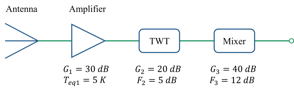
Figure 7: Circuit diagram for Pb-22
Solution:
\small \begin{aligned} &\text{Here,} \\[2ex] & \quad T_{eq1} = 5 \ K \\[2ex] & \quad \Rightarrow (F_1 - 1)T_0 = 5 \\[2ex] & \quad \Rightarrow (F_1 - 1) \times 290 = 5 \therefore F_1 = 1.02 \\[2ex] & \quad \footnotesize{(G_1)_{dB} = 30 \ dB \Rightarrow 10 \log_{10}(G_1) = 30 \therefore G_1 = 1000} \\[2ex] & \quad \footnotesize{(G_2)_{dB} = 20 \ dB \Rightarrow 10 \log_{10}(G_2) = 20 \therefore G_2 = 100} \\[2ex] & \quad \footnotesize{(F_2)_{dB} = 5 \ dB \Rightarrow 10 \log_{10}(F_2) = 5 \therefore F_2 = 3.16} \\[2ex] & \quad \footnotesize{(F_3)_{dB} = 12 \ dB \Rightarrow 10 \log_{10}(F_3) = 12 \therefore F_3 = 15.85} \\[2.5ex] &\text{We know,} \\[2.5ex] & \quad F = F_1 + \frac{F_2 - 1}{G_1} + \frac{F_3 - 1}{G_1 G_2} \\[3ex] & \quad \phantom{F} = 1.02 + \frac{3.16 - 1}{1000} + \frac{15.85 - 1}{1000 \times 100} \\[2ex] & \quad \phantom{F} = 1.0223085 \\[3.5ex] & \quad \therefore NF = 10 \log_{10}(F) \\[2ex] & \quad \phantom{\therefore NF} = 10 \log_{10}(1.0223085) \\[2ex] & \quad \phantom{\therefore NF} = 0.0958 \ dB \\[2.5ex] &\text{Now,} \\[2.5ex] & \quad T_{eq} = (F - 1)T_0 \\[2ex] & \quad \phantom{T_{eq}} = (1.0223085 - 1) \times 290 \\[2ex] & \quad \phantom{T_{eq}} = 6.469465 \ K \end{aligned}
Congratulations! You’ve successfully navigated the essential principles of Noise in Communication Systems. This is a critical step toward ensuring signal integrity and mastering the complexities of modern communication engineering. If any of these concepts, from thermal and shot noise to Noise Figure and Noise Temperature calculations, still feel a bit confusing, don’t hesitate to reach out. Drop a comment below with your questions, and let’s clear up the confusion together!
Read Also: Basic Concepts of Communication Systems